Receiver Port Mapping Guide
This guide will provide an overview on the receiver Port Mapping feature, and how it differentiates from channel assignment on the transmitter.
Supported Devices
Transmitters
Supported transmitters include the following
iX20 (with app version 1.10.11+)
iX14 (with app version 1.02.11+)
All NX Radios (with firmware version 3.13+)
Receivers
Supported receivers include the following (with firmware 3.4.0+)
Intro
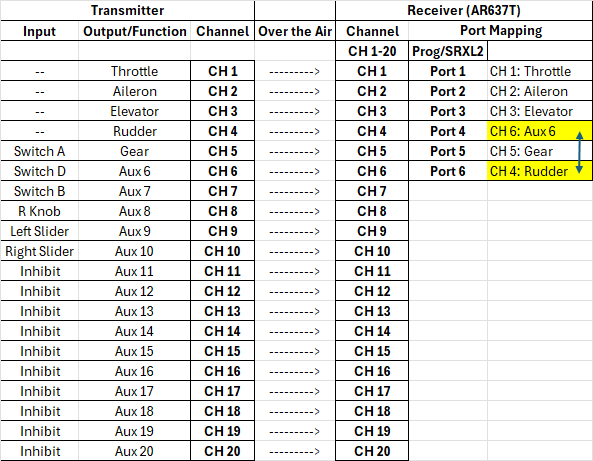
Port Mapping is a receiver feature which allows re-assigning or duplicating channels across different receiver ports.
By default, a receiver has the transmitters respective channel assigned to the matching port number.
SRXL2 outputs match the Transmitter Channel Assign order. The SRXL2 outputs are unaffected by Port Mapping. For a SMART ESC to work on a SRXL2 port (typically port 1 or a dedicated prog/srxl2 port), throttle MUST be assigned to Channel 1 on the transmitter, regardless of Port Mapping on the receiver.
Note that when using the Prog/SRXL2 port of the following receivers, the remote receiver SRXL2 port will be disabled.
AR6610T, AR637T, AR637TA, AR8020T, AR8360T
Location
This setting can be found in Forward Programming > Port Settings > Port Mapping.
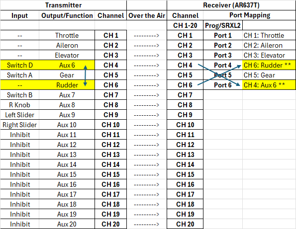
Note that if default channel outputs are re-assigned on the transmitter, they will show with ** in the Forward Programming selection menu’s.
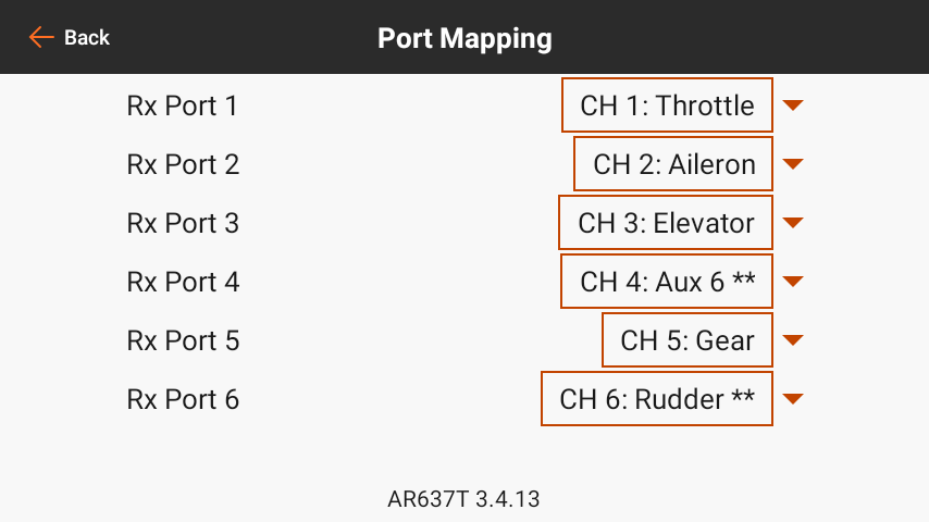
Receiver Port mapping assignment is unchanged, but CH4 and CH6 show ** indicating they have been reassigned on the transmitter Channel Assign menu.
Transmitter to Receiver Control Flow
In the communication chain between transmitter all the way to a servo output, there are a few steps illustrated below.
Example below shows an AR637T receiver which only has 6 physical ports. However, it still receives all channels from the transmitter.
Transmitter Side
Starting from the transmitter, the pathway is as follows
TX: Input - Physical input such as a switch or slider
TX: Output/Function - A more complex input which encompasses more than just the physical input, such as Throttle, Aileron, Elevator, or Rudder.
TX: Channel - The channel is the pathway through which an input and/or function data is transmitted to the receiver over the air.
Receiver Side
The receiver gets its data over the air packaged into “Channels”.
RX: Channel - The channel on the receiver is the same as the channel data received from the transmitter. Receivers receive all channels from the transmitter even though they are not all transmitted to a port. Channels that the receiver has access to, but does not output on a port are sometimes referred to as “Virtual Channels”
RX: Port - The actual physical port on the receiver that outputs a servo pwm pulse or other format of data if supported (such as SRXL2).
Flow Examples
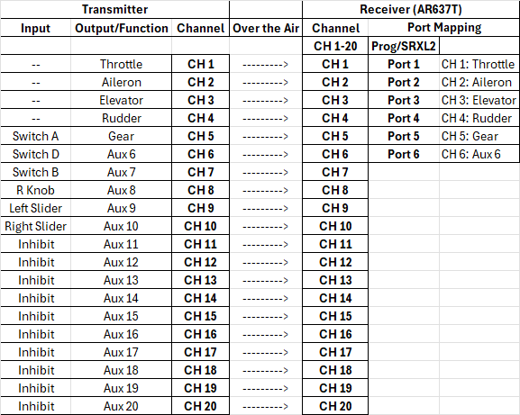
Channel Assignment
In this example, Aux 6 and Rudder are swapped on the transmitter side channel assignment. Without changing port mapping, this leads to Aux 6 outputting on Receiver Port 4, and Rudder outputting on Receiver Port 6. Note that Port 4 and Port 6 are still outputting CH 4 and CH 6 respectively, but what is sent over those channels has changed.
Note that when functions are channel reassigned on the transmitter from their default channel, they will show with ** in the Forward Programming selection menu’s.
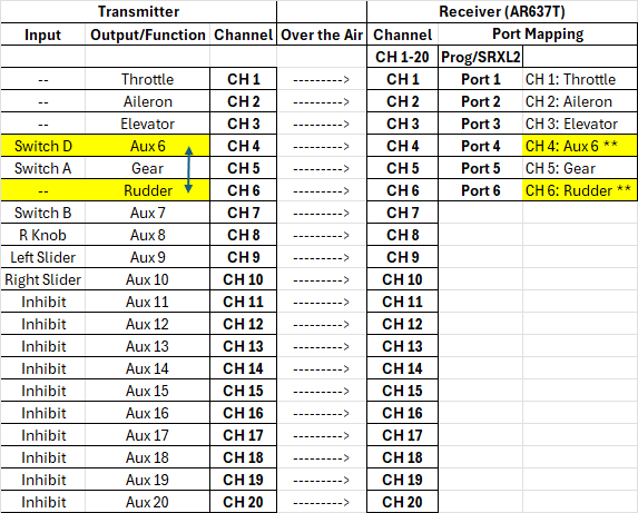
Port Assignment
In this example, Rudder and Aux 6 remain on their original channels, but we are swapping the channel assignment of CH4 and CH 6 on the receiver side with port mapping. The outcome at the port outputs is the same as the previous example in terms of what function ends up on what receiver port. However, note there are no ** next to the channels as the functions are assigned to the default channels on the transmitter side.
Channel Assignment and Port Assignment
In this example, we’re combining the channel assignment and port assignment from the previous examples. On the transmitter side, Aux 6 and Rudder are swapped in the channel assignment. On the receiver side, CH4 and CH6 are swapped on the port mapping side. The outcome on the servo port side is essentially as if nothing had been changed, though internally things are technically different.
Port Mapping vs Channel Assignment
When to use Port Mapping
Freeing up servo port 1 by using a SMART ESC on another compatible port (such as prog/SRXL2 port on some receivers)
To duplicate a channel. As an alternative to a servo y splitter (especially if high current is needed to both servos on the splitter)
Swapping channels so the ESC reverse channel doesn’t take up one of the receiver ports
When to use Channel Assign
If individual output parameters are needed (subtrim, travel, reversing, etc)
If an SRXL2 devices requires functions being on specific channels
Throttle must be on channel 1
ESC Reverse channel can currently only be on channels 5 to 9
Examples
Example 1: Getting an extra Servo/PWM port when using a SMART ESC
In this example, we’re setting up dedicated nosewheel control on CH7, assigning CH 7 to Port 1 through port mapping, and moving our SMART ESC to the Prog/SRXL2 port. The main thing to keep in mind here is with SRXL2/SMART communication, the ESC will always look at CH 1 for Throttle, so make sure the Throttle is still assigned to CH 1 on the transmitter! By having a dedicated channel for the nosewheel, we can configure stabilization for it as well as trim it independently from our rudder. See our Nosewheel Setup Guide for details on Nosewheel stabilization.
When changing the ESC port, always verify functionality WITHOUT a propeller!
Note that when using the Prog/SRXL2 port of the following receivers, the remote receiver SRXL2 port will be disabled.
AR6610T, AR637T, AR637TA, AR8020T, AR8360T
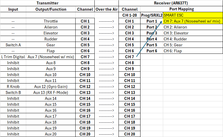
Moving SMART ESC to SRXL2 port to free up a servo port
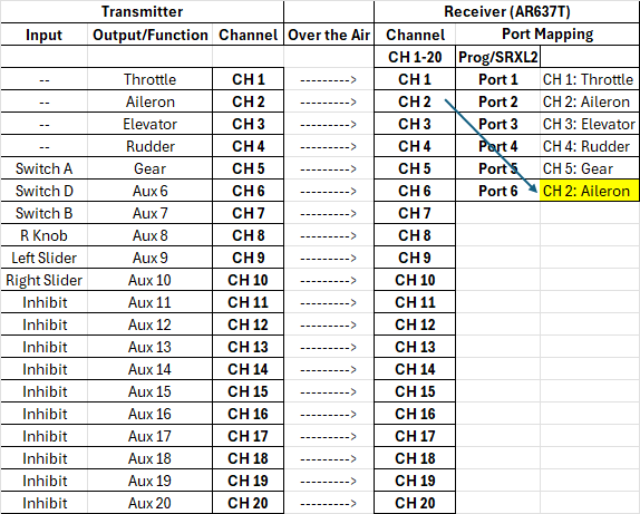
Example 2: Alternative to Y-Splitter
In this example, CH2: Aileron is mapped to Port 6. Since CH2 also remains assigned to port 2 as well, the channel is essentially duplicated on 2 ports. This effectively the same as using a Y splitter on Port 2 originally. The main benefits would be less wiring and better current throughput to each individual servo. This also frees up CH 6 to be used as a “virtual” channel.
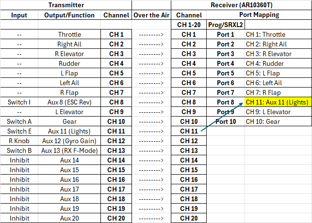
Example 3: SMART ESC Reversing without using up a receiver port
Since SMART ESC’s currently only allow using up to CH 9 to trigger the reverse function, it can take up a receiver port that can otherwise be used for another function. In this case, “CH 8: ESC Reverse” is unmapped from port 8, and is instead replaced with CH 11 to connect to our models light controller. CH 8 now becomes a “virtual channel” as its no longer tied to a port. However, it will still be seen on the SRXL2 stream so it can drive our esc reverse function.